
Alignment Services
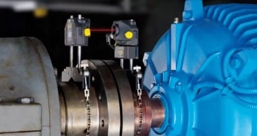
BAFCO-Reliability capabilities also include rotating shaft alignment. With the use of our precision laser systems, we can provide complete shaft alignment both vertical and horizontal including multiple coupled drivelines up to 12″ diameter and more.
Our team is capable of performing several alignment jobs like Bore alignment, Geometrical alignment, Cardan shaft alignment, etc.
The Importance of Laser Alignment
It’s estimated that 50 to 70 percent of vibration issues in rotating machinery are caused by misalignment. While misalignment has no quantifiable effect on motor efficiency, correct alignment does ensure you have a smooth and efficient transmission of power from the motor to the driven equipment, according to research on motor shaft misalignment by the University of Tennessee’s Maintenance and Reliability Center (MRC). Misalignment creates excessive vibration and high loads on bearings, mechanical seals, packing and couplings, impacting the operating life of rotating equipment. Other effects of misalignment are:
- Lost production
- More frequent repair orders
- Increase in spare parts purchases
- Low-quality products
BAFCO- Reliability technical team use modern laser alignment tools that check for three types of misalignment: parallel (offset), angular and a combination of the two. Both of the two main types (parallel and angular) can occur in vertical and horizontal planes.
1. Parallel (offset) misalignment
occurs when the centerlines of the two shafts are parallel but not in the same line. Shafts may be offset horizontally, meaning they’re offset to the left or right; or offset vertically, meaning they’re positioned at different heights.
2. Angular misalignment
occurs when the motor is offset at an angle in relation to the driven equipment. For example, if you were to draw an imaginary line from the centerline of the motor shaft and the centerline of the driven equipment shaft, the two lines would eventually cross rather than run along a common centerline. Angular misalignment can be horizontally or vertically misaligned. This type of misalignment can cause measurable damage to both the motor and driven equipment shafts over time.
3. Combination misalignment
is a combination of misalignment types that occurs when the motor shaft incurs both angular and parallel misalignment.
Balancing Services
BAFCO-Reliability also provides balancing services. The balancing of rotating bodies is important to avoid vibration. Dynamic and Static Balancing in Heavy Industrial machineries such as generators and motors can cause catastrophic failure, as well as noise and discomfort. To help with balancing, it involves simply moving the centre of gravity to the centre of rotation. For systems to be completely balanced both the force and couple polygons should be closed.
What is Static Balancing?
Static balance occurs when the center of gravity of an object is on the axis of rotation. This allows the object to remain stationary, with the axis horizontal, without the application of any braking force. Static balance has no tendency to rotate due to the force of gravity.
What is Dynamic Balancing?
Dynamic balancing is when the rotation does not produce any resultant centrifugal force or couple. The system will rotate without needing the application of any external force or couple, other than that required to support its weight. When a system or machine is unbalanced, to avoid stress being put upon the bearings, a counterbalancing weight is added. Dynamic balancing is a way to balance out machines by rotating parts quickly and then measuring the imbalance using electronic equipment. The imbalance calculated can then be added or subtracted from the weight until the vibration of the parts is reduced.
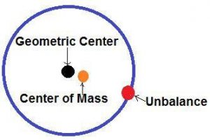
What is Unbalance?
Rotor unbalance can be defined as a condition that exists when the geometric center and the center of mass (also known as the center of gravity) do not coincide. In reality, these centers never coincide exactly, but the goal of rotor balancing is to reduce the unbalance to the point that machine life is not negatively impacted by the residual unbalance.
The balancing technician attempts to bring the center of mass and the geometric center to the same point or close enough to meet a predetermined balance standard. There will always be some residual unbalance.
Balancing Standards
Several standards organizations have developed balancing standards for use on various machines. ISO and API are a couple of examples.
These standards will allow you to achieve the required machine life and preserve equipment functions to the levels required by your processes. This may sound like a political answer, but in reality, the standards may vary depending on your plant’s requirements. The requirements will already be known if you are using a well-defined physical asset management process.
Unbalance is measured in units of ounce/inches or gram/millimeters. However, when you balance in the field, you usually balance to a vibration standard because it is easier to determine machine vibration levels than to determine residual unbalance.
The vibration due to unbalance is directionally proportional to the amount of unbalance. If the vibration levels due to unbalance are lowered to an acceptable level, the amount of unbalance is also brought to within an acceptable standard.
Forces Incurred by Unbalance
- Unbalance produces rotor vibration.
- Double the amount of unbalance, and the forces due to unbalance double.
- Double the rotor speed, and the forces quadruple.
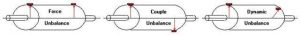
Types of Unbalance
- Static or force
- Couple
- Dynamic or a combination of force and a couple
Causes of Rotor Unbalance
- Blowholes in cast parts
- Eccentricity
- Improper key length
- Stress relief distortion
- Thermal distortion
- Corrosion or uneven wear
- Deposit build-up and component shift
- Asymmetrical design and assembly errors
- Rotor damage
- Repair work errors such as use of wrong coupling bolts or washers
Balancing is performed after acquiring vibration and phase measurements. There are three requirements for balancing: steady vibration, steady phase, and the vibration and phase measured must be due to rotor unbalance.
Before attempting to field balance a rotor, follow these basic steps:
- Perform a vibration analysis on the machine.
- Take radial and axial vibration readings.
- Ensure the rotor is clean.
- Verify there are no loose parts on the rotor.
- Always correct other problems before attempting to balance.
- Use a dial indicator to check total indicated runout (TIR).
- Remove previous balance correction weights.
Data collectors/analyzers such as the ADASH VA3 Pro can be used to perform the vibration analysis necessary to identify unbalance.
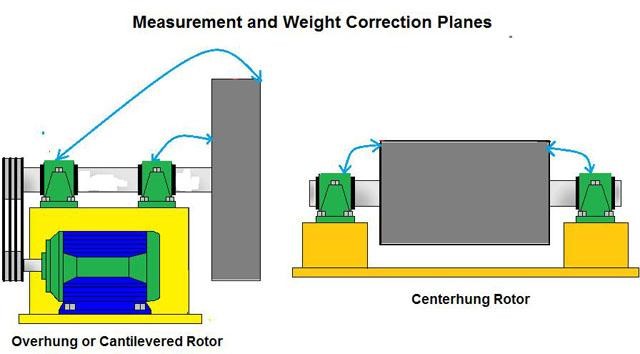
Unbalance is a radial force and produces a vibration frequency equal to shaft speed. The radial force can sometimes produce a vibration in an axial direction, especially in overhung or cantilevered rotors.
In these rotors, the axial vibration may be even greater than the radial vibration. The radial force causes the shaft to deflect, producing an axial direction vibration in the bearings.
Normally, unbalance will produce a 1× or shaft speed vibration that is 80 percent or more of the total vibration. If 1× vibration is less than 80 percent, suspect other problems in addition to the unbalance.
This is the same as stating that the vibration at other frequencies should not exceed 20 percent of the overall vibration. It may be necessary to correct the other problems before the rotor can be properly balanced.
Unbalance always exerts an equal force in all radial directions, but the vibration due to the unbalance is almost never equal in all directions. The horizontal vibration is usually the highest in amplitude because most machines are less stiff in that direction. Be careful because there are exceptions such as looseness in the bearings and vertical resonance.
If vibration amplitudes in the radial positions differ by 5:1 or more, other problems usually exist. If more than three harmonics of shaft speed are visible in the spectrum, other problems could be present, with the most likely being looseness. All other problems should be corrected before attempting to balance the rotor. The image below shows the corresponding measurement and weight correction planes.
Phase Indications of Rotor Unbalance
Phase is a very important tool when diagnosing unbalance because 1× vibration can be generated by several other problems. Phase numbers shown below may vary by 15 degrees.
Force unbalance phase difference:
0 degrees when comparing the same radial positions on two bearings.
Couple unbalance phase difference:
180 degrees when comparing the same radial positions on two bearings.
Dynamic unbalance phase difference:
0 to 180 degrees when comparing the same radial positions on two bearings.
The phase shift from horizontal to vertical should be approximately 90 degrees for all types of rotor unbalance when measured on the same bearing. The phase should be steady and repeatable when attempting to balance. (It may become unstable after a trim balance because other problems tend to become more dominant.)
A good indication of unbalance is that the phase difference between inboard horizontal (IBH) and outboard horizontal (OBH) should equal the phase difference between inboard vertical (IBV) and outboard vertical (OBV).
Phase errors drastically affect balancing. For example,
- A phase error of 7.5 degrees may produce an 8:1 vibration reduction.
- A phase error of 15 degrees may produce a 4:1 vibration reduction.
- A phase error of 30 degrees may produce a 2:1 vibration reduction.
- A phase error of 60 degrees or more may produce no reduction in vibration.
Balancing Rules
All rotors regardless of their diameter/width (D/W) ratio should be balanced in two planes.
However, on overhung rotors, if vibration in the bearing nearest the overhung mass has an amplitude of approximately four times the vibration in the other bearing, single-plane balancing may work. Overhung rotors with a D/W ratio of 4:1 or more may sometimes be balanced within the tolerance by a single-plane balance.
In addition, sometimes narrow overhung rotors don’t respond well to two-plane balancing. On overhung narrow rotors, it becomes more difficult to separate the influence of the two weight planes on the two measurement planes. This is simply because narrow rotor weight planes are in close proximity to each other.
To determine if a two-plane balance job is needed, set up and take four measurements but enter only one correction plane (single plane). Ask the program for estimated reductions.
If the estimates are within tolerance, continue with a single-plane balance. If the estimated reduction is out of tolerance, change the setup to two correction planes and continue.
Other Indications of Rotor Unbalance
The time waveform should contain a strong sine wave component. Acceleration measurements distort the time waveform because higher frequencies are amplified.
Steady phase and steady amplitude are also requirements for balancing. If either is not steady, don’t diagnose the problem as unbalance. Sometimes it may be wise to make vibration measurements and then shut down the machine. Start the machine again and see if the vibration and phase measurements can be duplicated.
Selecting a Proper Trial Weight
Proper trial weight (TW) selection is important because a weight that is too light may not provide an adequate response for calculating correction weights and placement. A trial weight that is too large may wreck the machine. Trial weights should adhere to the 30/30 rule: change the phase by 30 degrees or the amplitude by at least 30 percent.
Calculating Trial Weights
F = Rotor weight × 10 percent
F = (1.77) × (TW) × (R) × (rpm ÷ 1,000)2
Where: F = Force in pounds, TW = Trial weight in ounces, R = Radius in inches
Example: 5,400-pound rotor, 1,800 rpm, 13.5-inch radius
F = 5,400 × 10 percent; F = 540
540 = (1.77) x (TW) x (13.5) x (3.24)
540 = 77.4 TW
TW = 6.98 ounces
Typical Single-Plane Procedure
- Set up equipment on the rotor as outlined by the balance equipment manufacturer.
- Make “reference run” or “calibration run,” measuring vibration and phase.
- Add trial weight.
- Make trial run.
- Remove trial weight.
- Add correction weight.
- Make trim run.
- Add trim weight if needed.
- Make no more than two trim runs. If more than two trim runs are needed to achieve the standard, leave all weights in place, erase the data collected on this balance job and begin the process anew.
Typical Two-Plane Procedure
- Set up equipment on the rotor as outlined by the balance equipment manufacturer.
- Make “reference run” or “calibration run,” measuring vibration and phase.
- Add trial weight to plane #1.
- Make trial run #1.
- Remove trial weight from plane #1 and place on plane #2.
- Make trial run #2.
- Remove trial weight from plane #2.
- Add correction weights to planes #1 and #2.
- Make trim run and add trim weights if needed.
- Make no more than two trim runs.
- If balance job is not within specs after two trim runs, leave weights in place, erase the data collected on this balance job and begin the process anew.
When rotors will not stay in balance, the following problems should be suspected:
- Thermal sensitivity
- Operating near a resonance
- Rotor erosion
- Material build-up
- Speed changes bringing the machine into a resonance condition
- Loose rotor part
The mindset of “It’s a fan and it shakes so it must need balancing,” is referred to as the balancing syndrome and can get you into trouble. Here are some tips that will help you avoid such pitfalls.
- The time signal should not be too distorted from sinusoidal.
- The shaft speed vibration amplitude should be steady and repeatable.
- The phase should be steady and repeatable.
- No more than three harmonics of shaft speed should be present in the spectrum. (Plain bearings may be an exception.)
- There should be no raised noise floor.
- No sub-harmonics should be present.
- The rotor should be clean and free of build-up.
- Balancing should be the last corrective measure (correct obvious problems first).
Rotors do not become unbalanced without a cause. If a rotor has been acceptably balanced and becomes unbalanced, always try to detect and correct the root cause of the unbalance. Sometimes rotor-reinforcing gussets may crack, allowing the rotor to deform and resulting in a sudden unbalance.
If the rotor is rebalanced without repairing the cracks, sudden and catastrophic machine failure may occur if the gussets fail completely. Such problems can usually be avoided by performing a thorough cleaning and inspection.
Vibration is measured in displacement, velocity, and acceleration. Velocity and acceleration are generally the most often used units, but when you balance rotors, you usually use displacement measured in mils.
This is because displacement gives the best indication at low frequencies, and you are dealing with 1× shaft speed when balancing. The technician needs to be aware that 1 mil of vibration on a machine running at 900 rpm is not comparable to 1 mil of vibration on a machine operating at 3,600 rpm. There is considerably more force exerted on the 3,600-rpm machine.
Why a Balance Job Goes Wrong
The top causes for failing to achieve the required standard when balancing include:
- A mistake in setting up the data collector/analyzer
- Failing to remove a trial weight
- A problem that is not unbalance (usually looseness)
- Entering the trial weight location incorrectly into the balancing instrument
- Overhung load requiring two-plane balance
- Weight placement not in the proper direction with relation to the rotor direction
- Existing resonant condition
Becoming proficient at rotor balancing requires having good tools and being knowledgeable in their use. A fundamental knowledge of balancing theory and balancing procedures is also critical for success. Having a good grasp of vibration analysis will help to ensure that the technician performs balancing only when the problem is unbalance.
Because of many variables, there remains some art to balancing. With better tools and an improved knowledge, base balancing has become less of an art and more of an applied science.
SOURCE: